Detail 0-55MHz DDS VFO Signal Generator
This is a 0~ 55MHz DDS Signal Generator. It is based on AD9850 chip and is very easy to operate.
Supports 0~ 55MHz continual adjust at 1Hz step.
This generator has 78L05 voltage regulate. Input current at 200MA, input voltage 8-9V would be the ideal voltage.
Input voltage of 12V can only be used for short time testing, otherwise will cause heat to board.
5p/ 6p connect to encoder as per photo. 7p of the middle connects to digital matrix input. 14p ( 8V GND) is 8V power supply from main board. If powered by main board, DDS does not need independent power supply.
1~ 6 correspond to 6 frequency bands: ( 3.8� 7 � 9� 14� 18 or 21� 27 or 29)
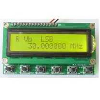
ISB, USB, CW are the three mode choices.
DT is signal from main board.
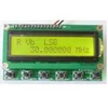
Pictrure Module Up & Buttom:
Picture Module Connection:
Keypad Panel instruction:
http: / / dropbox.indo-ware.com/ files/ produk_ indo-ware_ dds_ 9850_ k ecil_ pasang_ keypad.jpg
Keys & Connection interfaces:
ENC: encoder switch
MEM: switch for memory mode
VFO: Transfer from VFO A to VFO B, or from VFO B to VFO A.
SSB: Working mode change: circulate from USB, LSB, AM, CW, and on and on...
RIT: fine tuning to receiving frequency
CAL: set functions
KB-1 and KB-2 have common shared pin, but is not GND.
How to operate:
Press CAL, power on, then we enter setting screen. Let go/ release CAL.
A: ENABLE 6XREFCLE: setting chip clock mode, adjust frequency encoding setting. AD9851 set to 6-multiply frequency, AD9850 set to 1multiply frequency. Press CAL then quickly release to enter next step B.
B: DDS-SYSTEM-CLK: Chip working frequency setting. Use encoder switch to adjust value. Operate in accordance with STEP key. AD9851 set at oscillator 6-multiply channel, AD9850 set at actual output of oscillator. Press CAL then quickly release to enter step C.
C: MIN_ RX_ DDS_ FREQ� Setting minimum working frequency. Use encoder switch to adjust value and in accordance with STEP key. Press CAL then quickly release to enter step D.
D: MAX_ RX_ DDS_ FREQ� Setting maximum working frequency. Use encoder switch to adjust value and in accordance with STEP key. ( Smaller than 60MHz would be OK ) . Press CAL then quickly release to enter step E.
E: SSB_ OFFSET� Fine tuning for SSB working mode. Use encoder switch to adjust value and in accordance with STEP key. Press CAL then quickly release to enter step F.
F: CW_ OFFSET� Fine tuning for CW working mode. Use encoder switch to adjust value and in accordance with STEP key. Press CAL then quickly release to enter step G.
G: OFFSET_ FREQ� Setting of offset Frequency. e.g, set to 9MHz or 10.7MHz, use encoder switch to adjust value and in accordance with STEP key. Press CAL then quickly release to enter step H.
H: MULTIPLIER: multiply setting for frequency. Should be set as 1, press CAL then quickly release to enter step I:
I: Screen displayes word " SAVE" , automatically save the above setting, and returns to normal working.
Notes:
1. DDS SYSTEM CLK: can use frequency tester to get 30MHz oscillator, multiply the tested value at 6, then put the multiplied value here. If using AD9851, make initial setting at 180000000.
2. OFFSET FREQ: can be set as + or - . Rotate encoder switch to change value, press STEP key, then rotate encoder switch to adjust step. Minimum working frequency plus ( + ) offset frequency should be high than 0 ( zero) .
Frequency display:
RX = MULTIPLIER x ( RX_ DDS_ FREQ + OFFSET_ FREQ)
TX = MULTIPLIER x ( RX_ DDS_ FREQ + OFFSET_ FREQ + TX_ OFFSET_ FREQ)
The frequency programmed into the DDS, is calculated as shown below.
RX = ABS( RX_ DDS_ FREQ)
TX = ABS( RX_ DDS_ FREQ + TX_ OFFSET_ FREQ)
RX_ DDS_ FREQ, MIN_ RX_ DDS_ FREQ, MAX_ RX_ DDS_ FREQ, TX_ OFFSET_ FREQ & OFFSET_ FREQ
Examples:
1. DDS output range 30~ 40MHz:
MIN_ RX_ DDS_ FREQ MAX_ RX_ DDS_ FREQ OFFSET_ FREQ RX Frequency display range.
30 MHZ 40 MHz 100 MHz = 130 MHz to 140 MHz. Note 1
30 MHZ 40 MHz -10 MHz = 20 MHz to 30 MHz. /
-40 MHZ -30 MHz 170 MHz = 140 MHz to 130 MHz. Note 2
-40 MHZ -30 MHz 60 MHz = 30 MHz to 20 MHz. /
2. setting FT180A with DDS:
ENABLE RPT NO
X6 RECLK X6
DDS SYSTEM CLK 180M
MAX DDS FREQ 65M
MIN RX DDS FREQ 10.701M ( Offset frequency + RIT frequency)
MAX RX DDS FREQ 60M
TX OFFSET FREQ 0
MAX RIT OFFSET 1K ( RIT frequency)
OFFSET FREQ
10.700M
( Offset frequency)
MULTIPLIER 1
Gambar foto produk:
Circuit Rangkaian:
http: / / dropbox.indo-ware.com/ files/ produk_ indo-ware_ Schematic_ DD S_ Small.pdf
Project terkait module:
http: / / dropbox.indo-ware.com/ files/ ssb_ 6_ band_ www.indo-ware.com.rar
Referensi original desain:
https: / / docs.google.com/ viewer? a= v& pid= sites& srcid= aGFtcmFkaW8uaW58 cGNifGd4OjNkMmQ0MmIxNDJkMjE3ZmQ
http: / / pcb.hamradio.in/
Paket penjualan:
- 1 board module
- bonus Rotary Encouder EC11
- Cable EC11, & Cable DC power suply
- penjualan tidak termasuk " Keypad 3x4 Ruber" , link beli http: / / indo-ware.com/ produk-141-keypad-rubber-3x4.html
referensi BG6QBV deskripsi asli,
Tampilkan Lebih Banyak